
|
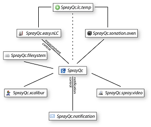
SprayQc.easy.nlc
The correct operation of all the components in the nano liquid chromatography (nLC) device is required to achieve high quality
chromatography. However, these components can fail and other problems can develop over the course of a measurement resulting in
diminished or corrupted data quality. To detect and provide early notification of such problems at an early stage, diverse metrics from
the nLC are continuously monitored. In all cases only a warning is issued to the operator, whose responsibility it then is to stop the
sequence, as it is currently not possible to control the data acquisition process and prevent further measurements. The early warning of
such events and consequent abortion of the runs by the operator already helps to preserve samples.
This view provides information on the liquid chromatography device.
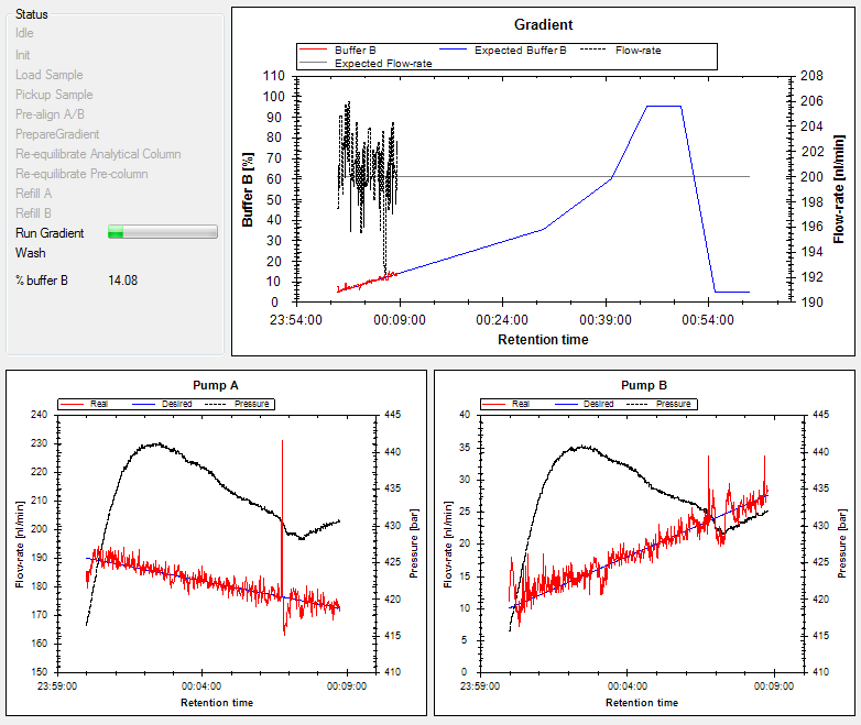
- A
This panel gives an overview of the actions (marked in black) are currently active on the LC (the inactive states are marked in grey). Where
possible, extra information is provided in the form of progress bars and additionally calculated information.
- B
This panel gives an overview of the programmed gradient (solid blue line) and flow-rate (solid black line). Additionally, the real gradient
(solid red line) and flow-rate (dashed black line) are reported as these values come in through the link with the device.
- C + D
These panels give overview of the state of the pumps with the real (red solid line) and desired flow-rate (blue solid line) and the pressure
(black solid line).
This view gives an overview of all the metrics that are calculated from the incoming telemetry data from the nLC device. These metrics
are used to warn the operator if a problem occurs with the LC device (a problem is defined as when a calculated metric crosses a pre-defined
threshold, marked with a black horizontal line).
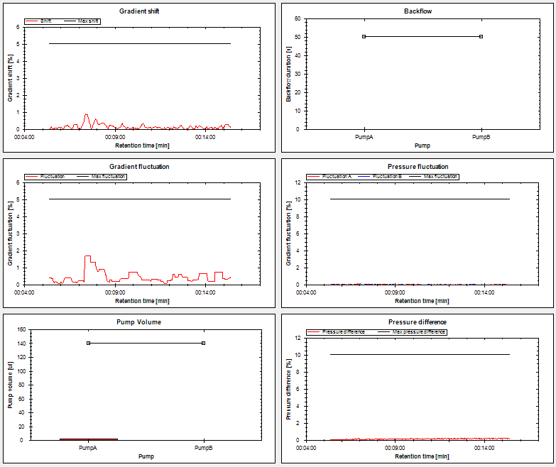
- A | Gradient shift
When mixing of the buffers is not correct, the real gradient can become shifted from the programmed gradient. How much the gradient is
shifted at each time in the gradient is displayed in the plot (red solid line). When the shift crosses the black line at 5% the operator
is warned.
- B | Gradient fluctuation
When mixing of the buffers still adheres to the programmed gradient, but fluctuates around the program (solid red line), stable chromatography
can be compromised and individual runs will be difficult or impossible to match together. When the fluctuation crosses the black line at 5%
the operator is warned.
- C | Pump volume
The syringes of the pumps have a limited volume of 140 µl, which cannot be refilled during the gradient without loss of pressure and stable
chromatography. For longer chromatographic runs it can occur that this volume is depleted. The bar-chart shows how much of the syringe volume
has already been used. When this crosses the black horizontal line the operator is warned.
- D | Backflow
When one of the pumps is compromised or broken, it will not generate sufficient pressure and a reversal of the flow is observed. When this
happens during the gradient, not stable chromatography is expected. The bar-chart shows the time in second that heavy backflow (> 5µl) is
observed. When this crosses the black horizontal line at 50s, the operator is warned.
- E | Pressure fluctuation
When the pressure is not stable, chromatography is also not expected to be stable. The fluctuation of the real pressure around the expected
pressure is displayed here (solid red and lines). When the pressure fluctuation crosses the black horizontal line at 10% the operator is warned.
- F | Pressure different
The pressures of the two pumps are expected to be the same over the complete gradient. When they start to deviate too much stable chromatography
is not expected. When the difference crosses the black horizontal line at 10% the operator is warned.
This view can be used to change the settings for this plugin.
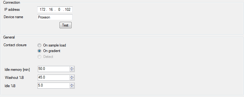
- Connection | IP address
The IP address of the nLC device. This requires that the device is connected to the same switch as the control PC (which is generally the
case). When SprayQc is run on a separate PC, this PC needs to be also connected to the same switch.
- Connection | Device name
Optional name for the LC, which can be used in reporting (in case different LC devices are used).
- General | Contact closure
The two options when the measurement is actually started. At this time this cannot be automatically detected and needs to be specified here.
- General | Idle memory [min]
The time in minutes during which the telemetry data is displayed in the graph when the nLC device is idling.
- General | Washout %B
The percentage of buffer B at which the washout phase starts.
- General | Idle %B
The percentage of buffer B to use between runs.
This view gives an overview of the method currently running on the nLC device. This view is not editable, and is only intended for evaluation purposes .
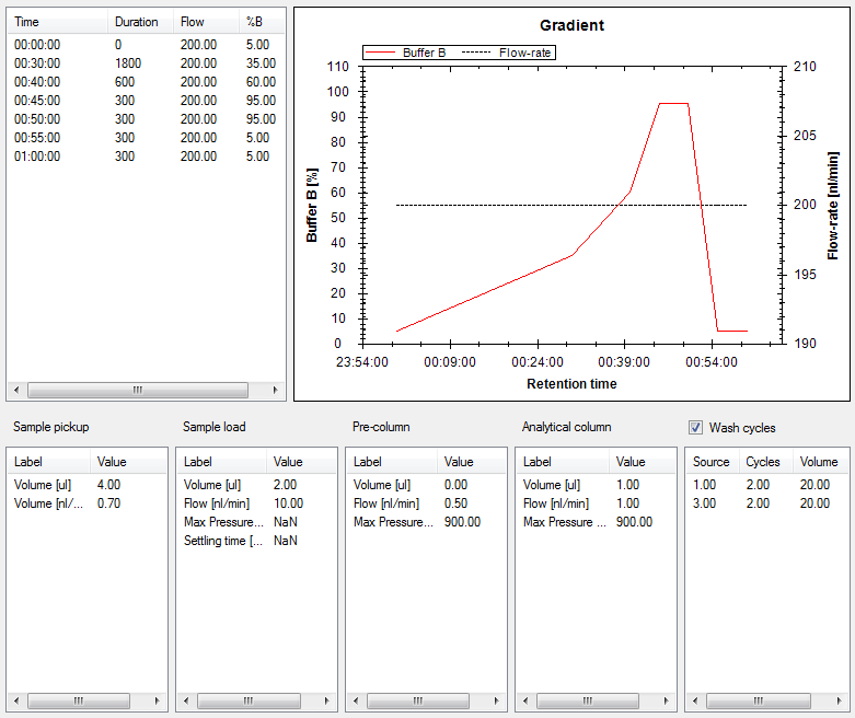
- A | Gradient program
This panel provides the gradient in values. For a graphical overview see panel B.
- B | Gradient program
This panel provides the graphical overview of the setup defined in panel A.
- C | Sample pickup
This panel provides the settings for the sample pickup.
- D | Sample load
This panel provides the settings for the sample load.
- E | Pre-column
This panel provides the settings for the pre-column.
- F | Analytical column
This panel provides the settings for the analytical column.
- G | Wash cycles
This panel provides the settings for the wash cycles.
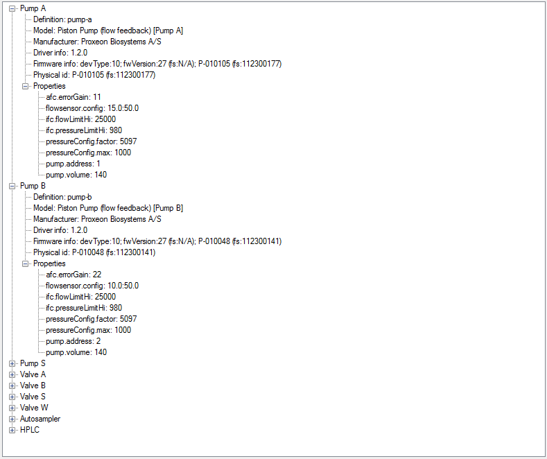
This view gives an overview of the configuration of the Easy nLC.
|
|